 Build")
Started building the OpenAstroTracker in November 2021 and completed it around April 2022. The OpenAstroTracker is an open source hardware project design of mostly 3d printed parts. The tracking stepper motors are driven using a 3d printer controller board running OpenAstroTech firmware. The initial investment in this rig was around $150 dollars in misc. parts and 3d printer filament.
Below are some pictures of the build as it progressed.
Printing and parts gathering
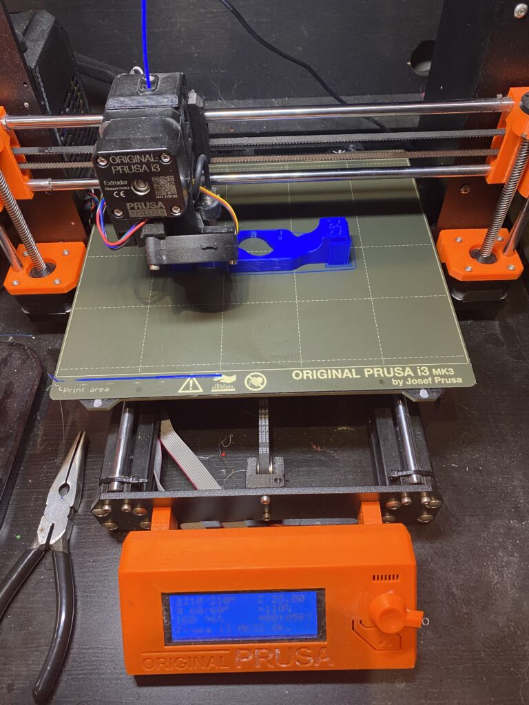
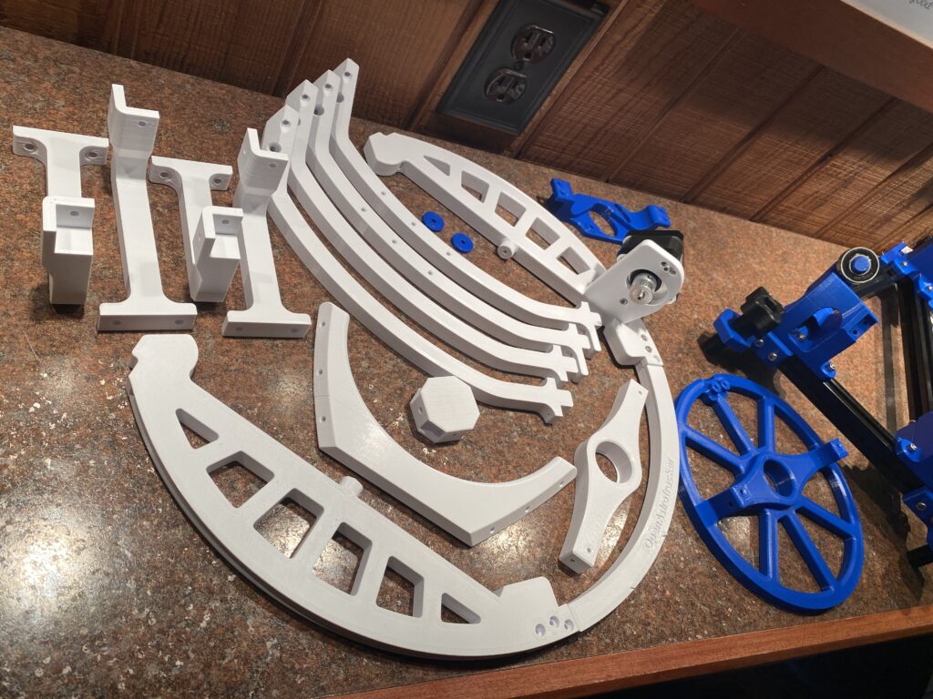
Assembly Progress
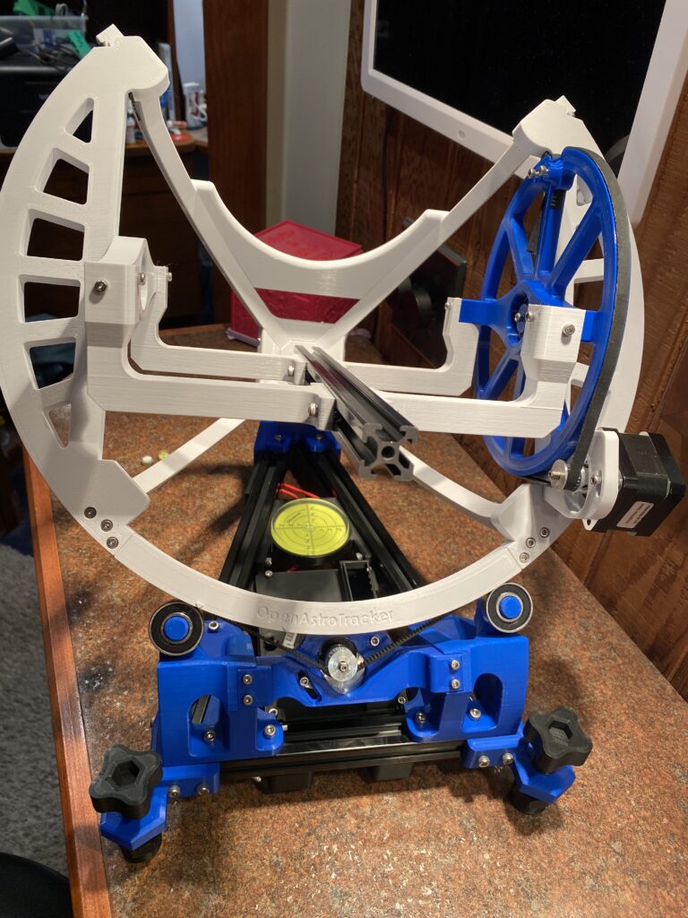
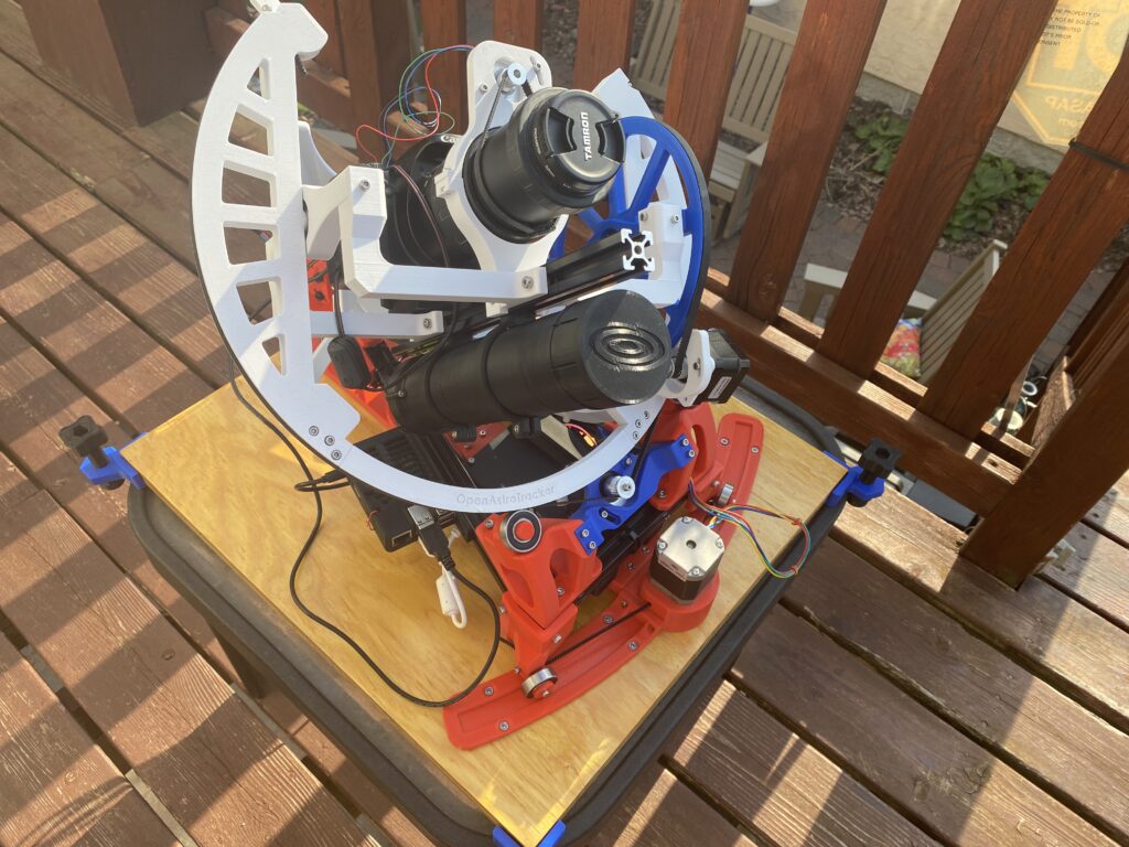
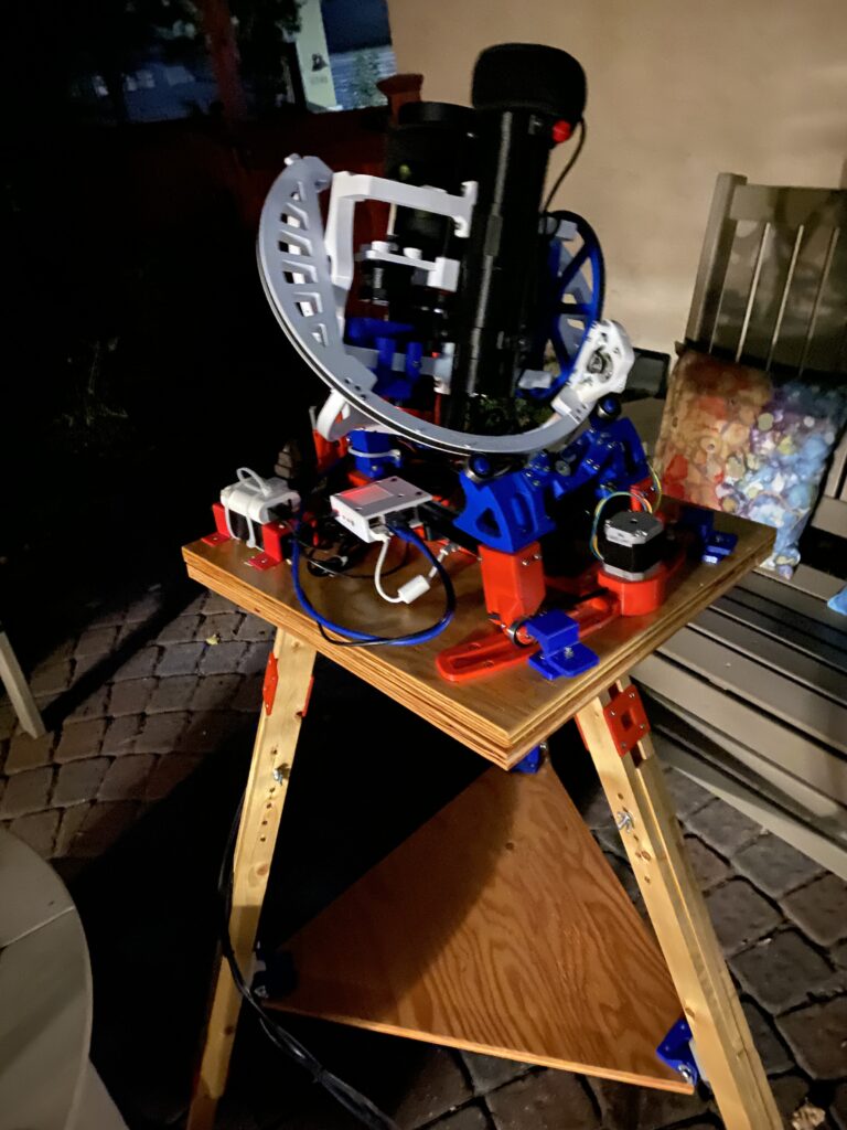
First picture below. The frame uses a few pieces of cut aluminum extrusion.
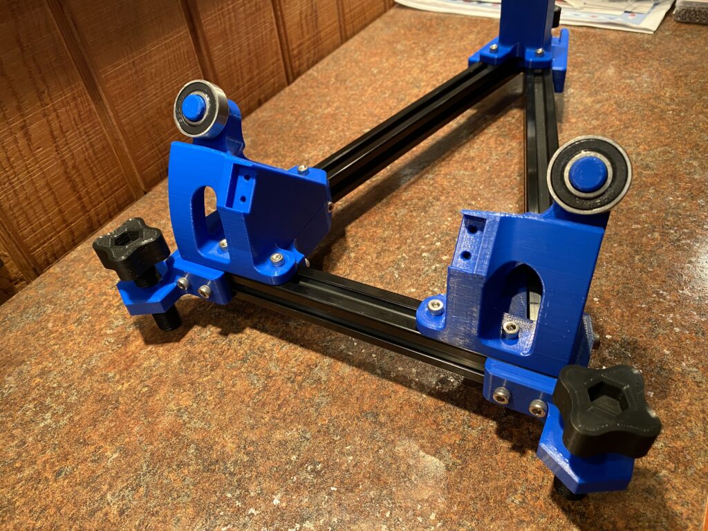
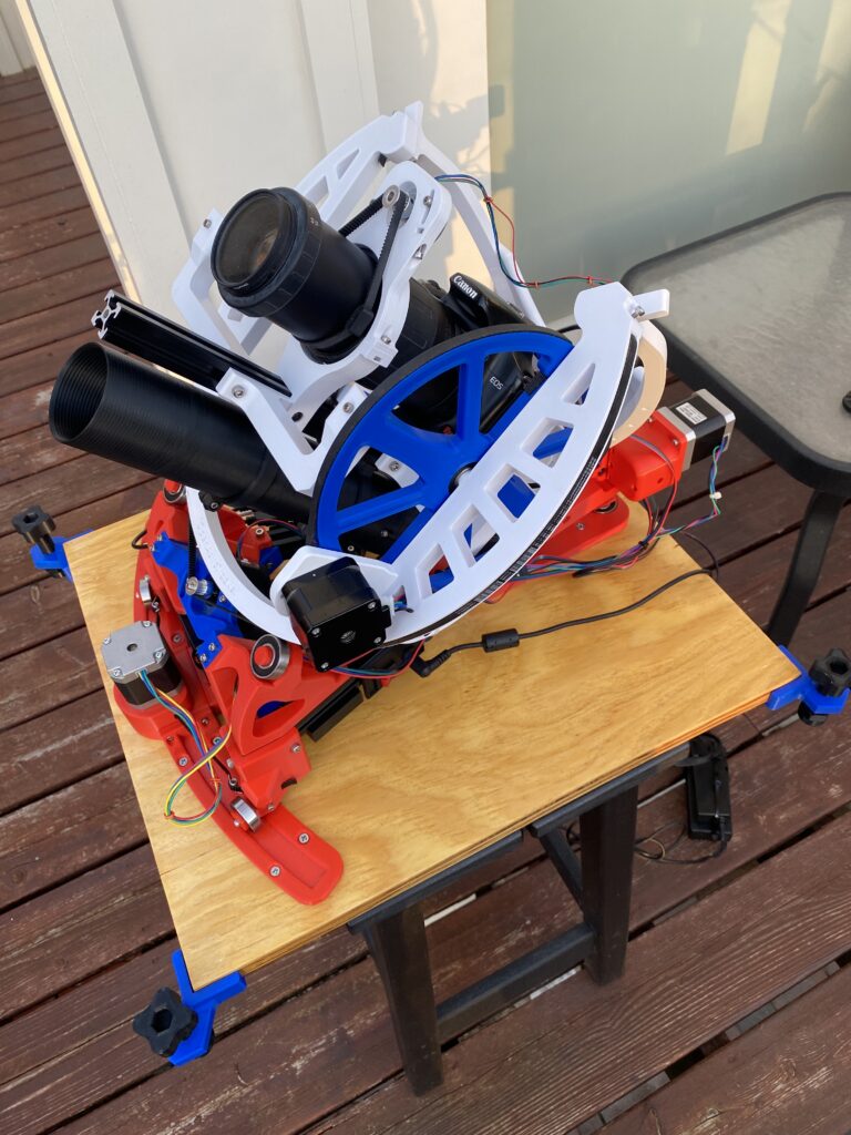
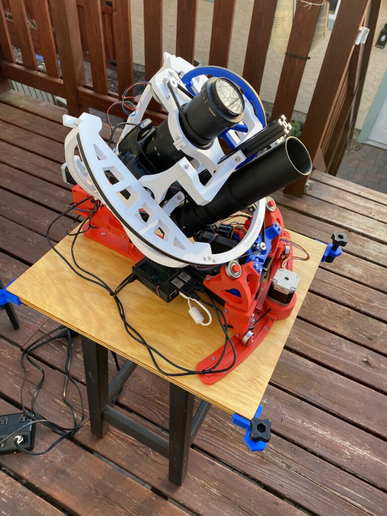
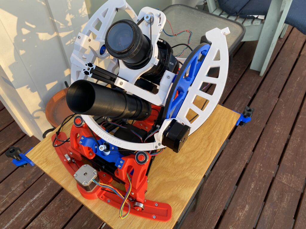
Second picture below, the large ring in the front is rotated with a stepper motor on the bottom in the middle picture. The smaller ring on the side is belt driven with another stepper motor visible on the right.
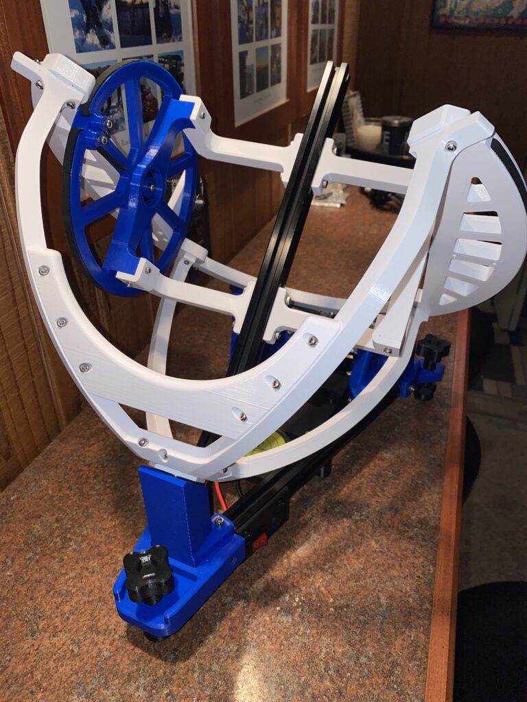
Third picture below, the payload, scope/lens, camera, guidescope, etc. are mounted to another piece of aluminum extrusion.
Electronics and Auto Polar Alignment Option
Before I even finished the build, I decided to build the auto-polar alignment upgrade option.
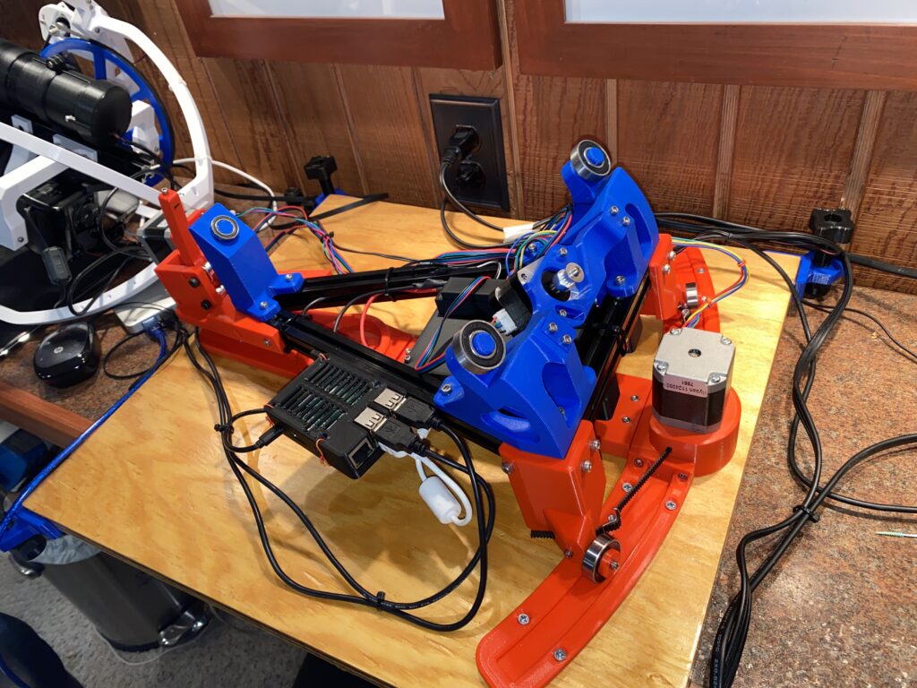
First pic below: The track for the auto polar option is the red semi-circle at the front of the OAT, it rides on bearings and moves left/right using the stepper motor attached to the frame using another belt.
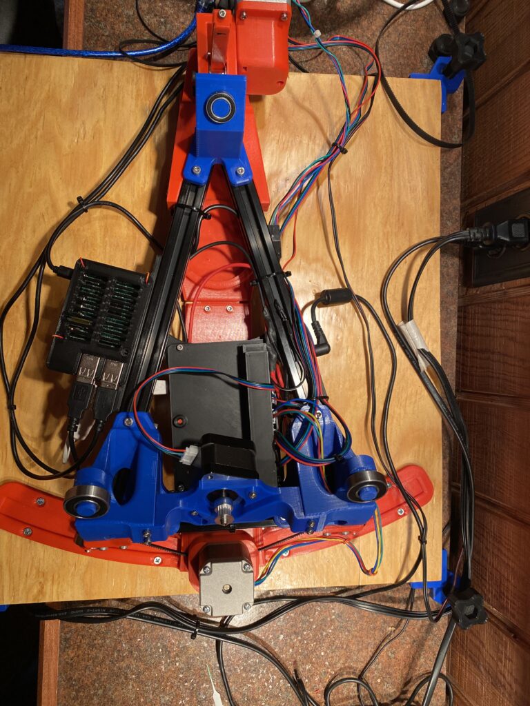
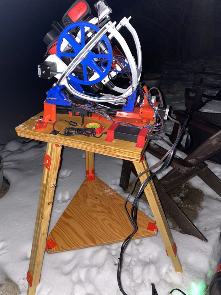
Second picture below: The second autoPA stepper motor, in the red gearbox enclosure in the back (top of picture) raises and lowers the whole frame from the rear. In this view you can also easily see the side mounted raspberry pi and the underframe mounted black box for the 3d printer stepper motor controller board.
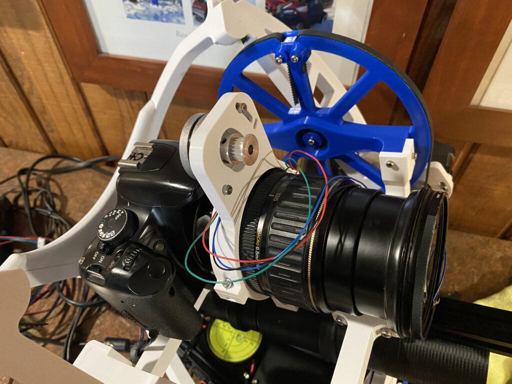
Auto Focus Option
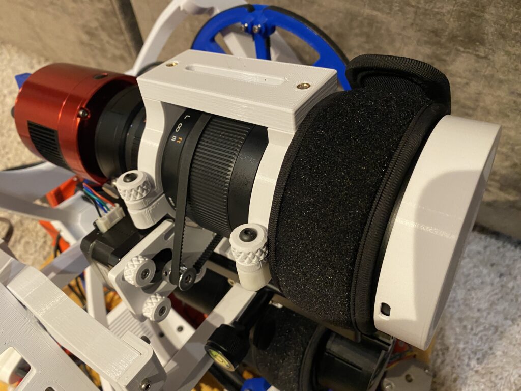
Initially my setup included a Canon 450D SLR and two different telephoto lens, all of which were “on hand”. Another small stepper motor is used to focus the lens. In the second picture it changed when I upgraded to a ZWO ASI533MC Pro color cooled camera (the red cylinder at the back). Not shown here, but the “final” upgrade that I did in December 2022 was a lens upgrade to a Samyang 135mm lens that is very fast at f2.0 and has very low chromatic aberration.
Completed Build, Guidescope and First Light
First imaging session was in the spring of 2022 of M81 and M82. Used a 200mm zoom lens. Took several nights to get polar aligned and focused. After all of the build effort, was pretty exciting to see it all working. You can also see the OpenAstroGuider (OAG) mounted under the camera and lens.
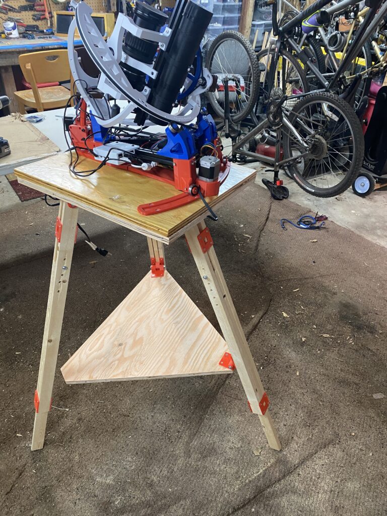
Tripod Build
I couldn’t find a reasonable DIY tripod online that I felt was sturdy enough, easy to build and suitable, so I designed one. A few designs I found online ones looked suitable for astrophotography, but they didn’t have adjustable legs, which I need due to some serious slope in my astro backyard.
The use of the printed hinges that use machine screws with butterfly nuts make it easy to disassemble into the two plywood pieces and the legs for compact storage and/or easy transport.
Tripod construction is made from 3/4 inch plywood, 1×2 inch trim boards and hardware that can be found at most local big box hardware stores. Printed parts are for joining the legs and creating the joints between the legs and the platform and between the platform and the spreader. https://www.printables.com/model/247962-astrophotographytelescope-tripod-with-adjustable-l
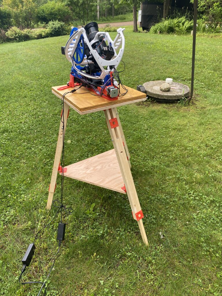
Additional Upgrades and Updates
Tripod. The tripod took a couple of iterations and failures before got to a design that worked well. Revised design is in the featured photo at the top, including beefier hinges and better print orientation so that they won’t break as easily. Also added some “feet” to the legs that can be used to do some additional leveling and make it more stable on soft ground.
Guidescope. Rebuild the guidescope to the newer open source design that had improved focusing capabilities, and in general just a better design.
Raspberry PI. Upgraded the Raspberry PI from a 3 to a 4 for improved performance.